Feedback Resistor Calculator | Delta Method
About Feedback Dividers
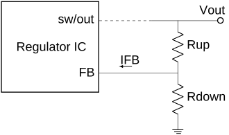
Feedback resistor dividers are commonly used to set the output voltage in DC-DC converters, such as buck, flyback, LDO, etc.
The regulator IC maintains a constant voltage VFB at the feedback pin to match its internal reference, while the resistors Rup, Rdown scale VFB to a higher target output voltage Vout. In practice, the internal error amplifier sinks or sources a tiny bit of bias current, known as feedback leakage current IFB, which creates an undesired offset (Rup IFB) in the output voltage.
When accounting all these parameters and their manufacturer tolerances, a traditional worst-case analysis often leads to over-engineering. This tool evaluates component tolerances through gaussian distribution model and calculates the Vout min/max using Second Order Delta Method, providing much more realistic and practical design data, matching the precision of Monte Carlo simulations
Besides this, there is a current IRdown that flows through Rdown which contributes to overall quiescent current of the converter. Minimizing IRdown is critical for battery connected converters. This tool will help designers choose resistors with best balance of statistical Vout accuracy and IRdown current.
| Rup ↕ | Rdown ↕ | Vout Min. ↕ | Vout Typ. ↕ | Vout Max. ↕ | Vout Acc% ↕ | IRdown ↕ | LT Spice |
|---|